Acquisition board
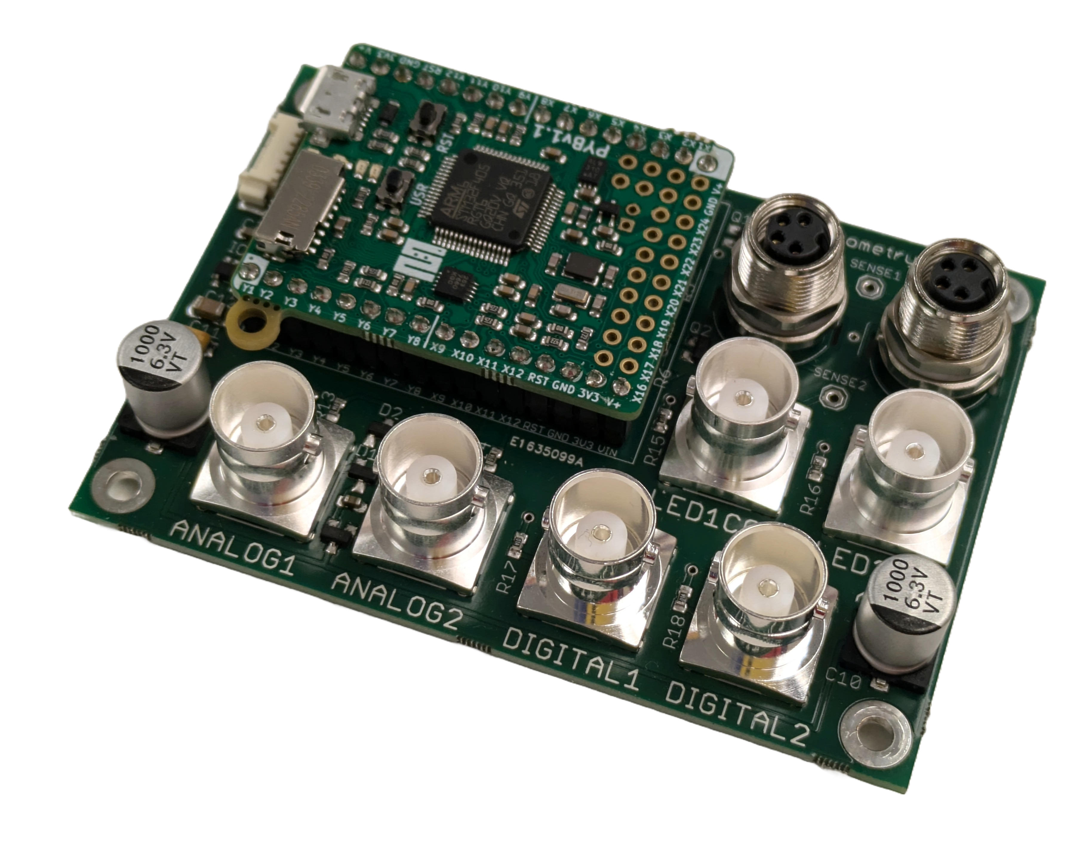
The pyPhotometry acquisition board uses a Micropython microcontroller to acquire two digital and two analog signals, and to generate analog control signals for two built in LED driver circuits. The acquisition board draws power from the Micropython's USB connector and requires no additional power supply.
Two versions of the acquisition board have been developed, v1.0 and v2.0. The principal difference between the boards are that the v2.0 board has supports higher LED driver currents, and has additional LED control outputs enabling it to be used with optical hardware that has integrated LED drivers such as Doric Gen 3 minicubes. For more information see below and the hardware GitHub repository.
Safety
To prevent short circuits due to contact with metal objects, the board should either be used with the Acquisition board case, or be securely mounted using M3 bolts and insulating spacers. The mounting holes on the acquisition board have a 50 x 75mm spacing so the board can be mounted directly on a Thorlabs metric optical breadboard using M6 to M3 thread adaptors.
Though the LED drivers are relatively low power, care should be taken to avoid shining light directly into the eye. This is particularly important with LEDs whose wavelength lies outside the visible spectrum.
Analog inputs
The two BNC analog inputs SIGNAL 1 and SIGNAL 2 receive fluorescence signals as analog voltages from the photodetectors. The signals pass through an RC lowpass filter with a cut-off frequency of 10KHz and then are read by the Micropython board's analog to digital converters (ADCs). The Micropython ADCs have a 0 - 3.3V input range. As the ADC pins are not 5V tolerant, clamp diodes to the 3.3V rail are used to prevent damage if the signal rises above 3.3V. Oversampling is used to increace the 12-bit resolution of the ADCs to 15 bits - i.e. to generate each sample the ADC is read 64 times and averaged, giving an extra 3 bits of resolution.
Digital inputs
The two BNC digital inputs are compatible with 5V or 3.3V logic and are typically used to acquire sync pulses or timestamps, e.g. generated by behavioural hardware. The digital inputs connect directly to pins on the microcontroller.
LED drivers
The acquisition board has two constant current LED driver circuits which are controlled by the pyboard's digital to analog converters (DACs). The v1.0 board supports LED currents up to 100mA, while the v2.0 board supports LED currents up to 300mA in pulsed mode and 200mA in continuous mode. The LED driver outputs are M8 connectors that are compatible with either Doric or Thor Labs connectorized LEDs.
The LED driver circuits are voltage controlled current sinks in which an op amp adjusts the voltage at an MOSFET's gate to bring the voltage across a sense resistor in series with the LED into agreement with the control voltage from the microcontroller. A resistor between the 3.3V rail and the inverting input of the op amp ensures the MOSFET is fully turned off when the control voltage is 0.
LED control outputs
The LED control outputs on the v2.0 board provide an analog control voltage signal (0-3.3V) that can be used to control optical hardware with build in LED drivers such as Doric Gen 3 minicubes. The signals output on the two LED control outputs are the same signals used to control the on-board LED drivers, so it is not possible to independently use the LED control outputs and the LED driver outputs at the same time.
Assembly instructions
Acquisition board
The acquisition board can be purchased from the Open Ephys store for €364 or built from components. The design files for the acquisition board are in the hardware repository. To assemble the board from components you will need to get the PCB printed (using either the Gerber or Eagle files) and order the electronic components listed in the BOM (Farnell part numbers are provided).
Assembling the acquisition board requires both surface mount and through hole soldering. The surface mount soldering can be done either using a reflow oven or hand soldering. Hand soldering of surface mount components requires a bit of practice but there are lots of tutorials online. Solder all the surface mount components before soldering the through hole components as once the through hole components are in place they will get in the way. The micropython board is attached to the acquisition board using the male and female 16 way headers. First solder the female headers onto the micropython board, then insert the male headers into the female headers, mount the micropython on the acquisition board and solder the male headers.
Optical components
To make a complete photometetry system the acquisition board needs to be paired with LEDs, photorecievers, and optical components, see the Optical Components docs for information about compatible optical components and parts lists for Red/Green photometry systems based on Doric Minicubes.
Modifying the pyPhotometry board for higher LED current
The LED drivers on the pyPhotometry v1.0 board can output up to 100mA currents. While this is fine for many applications, higher LED currently may be preferable in some cases - e.g. with constructs that need higher light intensities or use wavelengths where only less efficient LEDs are available.
With a simple modification to the board - changing one resistor value per LED driver, it is possible to increase the maximum current that can be used in the pulsed illumination modes up to 400mA. Modifying the board risks damaging it and is done entirely at users risk.
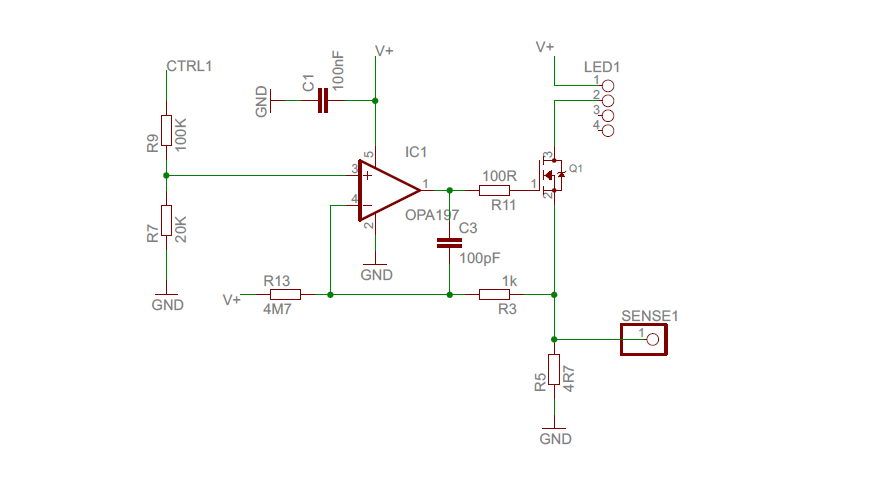
The schematic of the LED driver circuit is shown above. The current through the LED is controlled by the MOSFET Q1, whose resistance is determined by the voltage applied to its gate by the opamp IC1. The opamp adjusts the gate voltage, and hence LED current, to bring the voltage across the sense resistor (R5) into agreement with the voltage at the + input to the opamp, which is controlled by the pyboard DAC (connected to CTRL1). The LED current is therefore proportional to the control voltage output by the pyboard DAC, with a slope determined by the value of the sense resistor R5. If you halve the value of R5, the LED current for a given control voltage will be doubled.
The maximum current that can safely be output is limited by power dissipation in the MOSFET and sense resistor. LEDs typically have a forward voltage of 1.8-3.3V depending on the LED wavelength and current. The supply voltage is 5V, and the remaining voltage drop will occur across the MOSFET and sense resistor, dissipating power as heat. Higher LED currents result in more power dissipation and hence more heating, putting an upper limit on the current that can be delivered without damaging these components. This is approximately 200mA continuous current, but will depend a bit on the exact LED used, so limiting max currents to 100mA in continuous mode is recommended. However, in pulsed acquisition modes, each LED is only on for a small fraction of the time, hence both average current and power dissipation are much lower, and higher LED on currents are possible - we suggest 400mA as an upper limit.
To modify the system to use higher currents you can replace the 4.7Ω sense resistors R5 and R6 (for LEDs 1 and 2 respectively), circled in yellow on the diagram below with a 1.2Ω 0805 package resistor, e.g. Farnell part number 1717800.

Changing the resistor values from 4.7 to 1.2Ω without modifying the code will result in the actual LED currents being 3.9x higher than those specified in the GUI and data files. To correctly specify the LED currents, you can create a new device config file in config\devices for the modified board by copying the file pyPhotometry_v1.0.json but editing the LED_calibration slope variable from 38.15 to 9.78 and the max_LED_current for pulsed acquisition to 400mA from 100mA. Don't increase the maximum LED current in continuous mode to avoid overheating the LED drivers.